Step 2 - Fitting the resistors
Having sorted out your components its time to solder them onto the PCB. I always start with the smallest components first, moving up through the sizes till I come to the largest. This means that when you turn the PCB over to solder the part can be held more securely against your workbench, as opposed to flapping around.
You will need an iron with a small tip as some of the tracks are very close together. Its also a good idea to make sure you iron is fairly hot (mine is set to 600 °F / 340 °C), that way you can be a lot quicker, thus having less potential to damage any components.
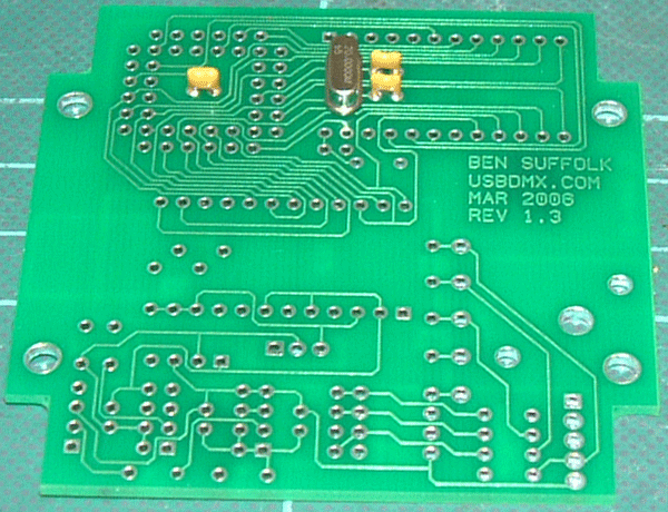
First off you will need to mount any of the components on the reverse of the PCB. For the 1.3 revision thats XTL1, C1, C2 & C4. Check your componenets for the 1.2 revision, none should need mounting on the back. Try and cut the leads as short as possible as you will be fitting components over them on the main side. I do this by cutting the component leads to size before soldering.

|
|
Revisino 1.3 underside components fitted
|
|
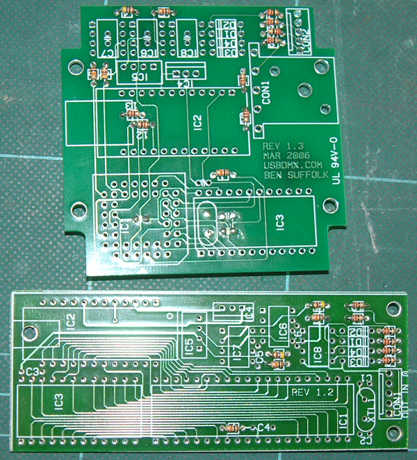
Once the underside components have been fitted, start the main side by mounting all the resistors. It should be noted that R10 is optional. This is the DMX terminating resistor for the DMX receiver. If you do not wish to place this on the end of the DMX line then it should be not be included. However its always good practice to terminate you DMX line, so make sure you use a termination plug on the last receiver.

|
|
PCBs with resistors fitted
|
|