Step 7 - The case
This page is related to the 1.3 PCB only.
The case is constructed for a number of different parts. These are heavy duty black powder coated steel and aluminium extrusions. They are part of a range called MSB from Penn Fabrication. Because I have used the MSB range there is nothing stopping you using the relevant parts to make this a 2U rack mounting device, or even combining several (upto 10) interfaces into a single 2U rack case (you could combine a powered USB hub inside the case).
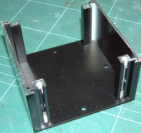
Start by screweing the side extrusions onto the base of the case. You wil use the larger screws for this.
|
|
The base and sides of the case
|
|
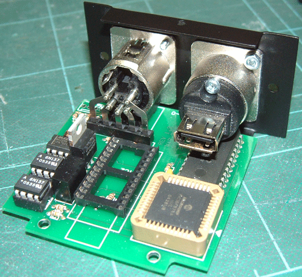
You wil fit the PCB to the fornt panel, along with the USB socket. The USB socket is revesable so you can decide if you want a type A or a type B on the outside of the box. Its normal however to have a type B socket on a device like this.
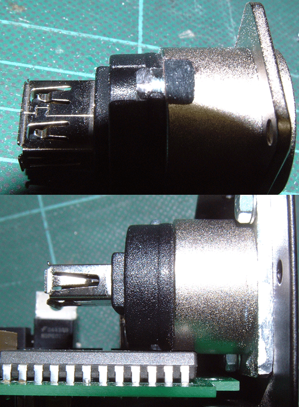
Before the USB socketc an be fitted it will need a small part filing off it, so that it can fit above IC3. Its important that you do this rather than straining the PCB by forcing it to fit.
|
|
The PCB fitted to the front panel
|
|
You may need to file it a few times and check how well it fits against IC3 before the final tightening of the screws. It may also be nessesary to file the edge of the USb socket that is facing the extusions. Sometimes the are a little oversized. Check it by sliding it into the case you have built.
|
|
The filed USB socket
|
|
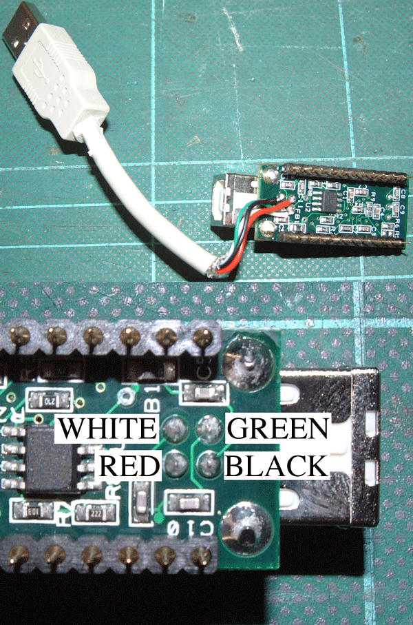
Now you will need to attach the USB lead. This is probably the most tricky part of the entire build. Take a USB lead and cut it (measure the length in the case to get it right, to long or to short could put strain on the joint) strip the sleving off it. You can also remove the shielded braid as this is not needed. I also removed the additional molded stain relief around the back of the plug. This will help it to fit in the case better.
You will need to solder the 4 wires from the lead onto the bottom of the USB module (IC2). Use a multimeter to make sure you get the wires onto the correct pins. I have shown the colours of the wires when I did it. Its likley that they will be the same, but please do check just incase.
|
|
Fitting the USB lead
|
|
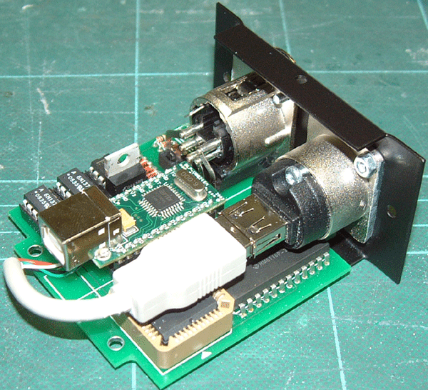
Once you have done that, fit IC2 int the socket and connect the USB plug into the socket.
|
|
The finished PCB
|
|
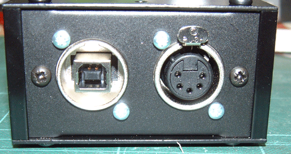
Slide the front and rear modules into the side extrusions and screw the top of the case on. Once the top is fitted you can screw the front and rear modules to the extrusions using the smaller screws. Then fit the rubber feet. The case is now complete.
|
|
The front module screwed into place.
|
|