Step 1 - The PCB
If you make your own PCB, check it over to make sure its not damaged, and no tracks are broken. Its also a good idea to remove the rough edges, from the manufacturing process, with a small file. This step is not neede if you buy the revision 1.3 PCB from the ordering page as they have been electrically tested, and cleaned during the manufacture process.

|
|
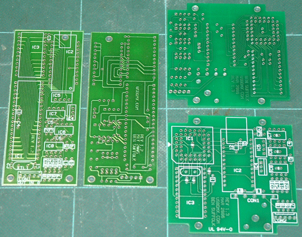
The revisino 1.2 and 1.3 PCBs side by side
|
|
The revision 1.3 PCB has been designed to be either mounted in the case via the XLR socket, or mounted via its 4 mounting holes into a difference case.
You should familierise yourself with the PCB and the positions of the components. Get the components and make sure you know which one is which, and where it goes. Removing components is not all that easy and its much better to spend some time getting them right in the first place.
On the 1.2 PCB all of the components will be fitted on the top of the PCB, however there is the possibility that R1 and C4 will need to be mounted on the underside. This will depend on wether you plan on using a socket to mount the microprocessor (IC1) in. My recommendation is that you do use a socket as this not only facilitates swapping it out if necessary, but also means you are not soldering directly onto the microprocessor so are a lot less likely to damage it.
The 1.3 PCB requires a few of the components tobe mounted on the underside. These are the Xtal (XTL1) and its 2 capacitors (C1 & C2), along with the smoothing capacitor for the microprocessor (C4).